WireGuard
WireGuard is an extremely simple yet fast and modern VPN that utilizes state-of-the-art cryptography. It aims to be faster, simpler, leaner, and more useful than IPsec while avoiding massive headaches. It intends to be considerably more performant than OpenVPN. WireGuard is designed as a general-purpose VPN for running on embedded interfaces and super computers alike, fit for many different circumstances. Initially released for the Linux kernel, it is now cross-platform (Windows, macOS, BSD, iOS, Android) and widely deployable.
Properties
| Property | Description |
|---|---|
| comment (string; Default: ) | Short description of the tunnel. |
| disabled (yes | no; Default: no) | Enables/disables the tunnel. |
| listen-port (integer; Default: 13231) | Port for WireGuard service to listen on for incoming sessions. |
| mtu (integer [0..65536]; Default: 1420) | Layer3 Maximum transmission unit. |
| name (string; Default: ) | Name of the tunnel. |
| vrf (string; Default: main) | Specify vrf for wireguard socket, more details below. |
| private-key (string; Default: ) sensitive | A base64 private key. If not specified, it will be automatically generated upon interface creation. Each network interface has a private key and a list of peers. |
The vrf parameter in WireGuard context
The vrf parameter does not apply to the WireGuard interface itself (e.g., wg0, wg1), but rather to the UDP socket used for transporting encrypted packets.
There are two distinct layers in WireGuard operation:
- WireGuard interface — this is the virtual network device through which plain (unencrypted) packets flow. These packets are encrypted and sent out through the UDP socket, or decrypted when they come in from it.
- UDP sockets — these handle the encrypted traffic: receiving encrypted packets from the network and sending encrypted packets out.
The vrf parameter is relevant to the UDP socket layer (case 2). It specifies which routing table (VRF) the socket should use to determine how encrypted packets are sent or received.
This ensures that encrypted traffic follows the correct routing path and uses the proper source IP, preventing issues where packets might otherwise go out via the wrong interface or route.
Example:
Suppose interface
eth1belongs to VRFfoo.
If you want WireGuard to send and receive encrypted packets viaeth1, you should configure WireGuard withvrf=foo.
It’s perfectly normal for the WireGuard interface (wg0) itself to be in a different VRF than the one specified by thevrfparameter used by the internal UDP socket.
Read-only properties
| Property | Description |
|---|---|
| public-key (string) | A base64 public key is calculated from the private key. Each peer has a public key. Public keys are used by peers to authenticate each other. They can be passed around for use in configuration files. |
| running (yes | no) | Whether the interface is running. |
Peers
| Property | Description |
|---|---|
| allowed-address (IP/IPv6 prefix; Default: ) | List of IP (v4 or v6) addresses with CIDR masks from which incoming traffic for this peer is allowed and to which outgoing traffic for this peer is directed. This IP address has to be in the same subnet as WireGuard interface set on ROS. If WireGuard interface is at 192.168.99.1/24, you have to input 192.168.99.2 to the client. By adding this IP under 'Allowed Address', you are saying that only this specific client (phone for example) is permitted to connect to this peer configuration. Allowed-address range cannot overlap on one interface, so you need to set your own range for each peer. |
| comment (string; Default: ) | Short description of the peer. |
| disabled (yes | no; Default: no) | Enables/disables the peer. |
| endpoint-address (IP/Hostname; Default: ) | The IP address or hostname. It is used by WireGuard to establish a secure connection between two peers. |
| endpoint-port (integer:0..65535*; Default:* ) | The Endpoint port is the UDP port on which a WireGuard peer listens for incoming traffic. |
| interface (string; Default: ) | Name of the WireGuard interface the peer belongs to. |
| persistent-keepalive (integer:0..65535; Default: 0) | The interval, in seconds, between 1 and 65535 inclusive, of how often to send an authenticated empty packet to the peer for the purpose of keeping a stateful firewall or NAT mapping valid persistently. For example, if the interface very rarely sends traffic, but it might at any time receive traffic from a peer, and it is behind NAT, the interface might benefit from having a persistent keepalive interval of 25 seconds. |
| preshared-key (string; Default: ) sensitive | A base64 preshared key. Optional, and may be omitted. This option adds an additional layer of symmetric-key cryptography to be mixed into the already existing public-key cryptography, for post-quantum resistance. It also can be generated automatically or entered manually, when the key is provided by the system administrator. |
| private-key (auto/none; Default: none) sensitive | A base64 private key. |
| public-key (string; Default: ) | A base64 public key is calculated from the private key. Each peer has a public key. Public keys are used by peers to authenticate each other. They can be passed around for use in configuration files. |
| show-client-config*sensitive | Will show the already-created Peer configuration and generate a QR code for easier peer setup on a client device. Does not affect the WireGuard Server. To view the QR code, show-sensitive is required from 7.21_ab548. |
| Used for the client-server setup scenario, when the configuration is imported using a qr code for a client, configuration details on the tab with qrcode will appear once it has been set in the fields: | |
| client-address (IP/IPv6 prefix; Default: ) | When imported using a qr code for a client (for example, a phone), this address for the wg interface is set on that device. |
| client-dns (IP/IPv6 prefix; Default: ) | Specifies when using WireGuard Server as a VPN gateway for peer traffic. |
| client-endpoint*(IP/IPv6 prefix; Default: )* | The IP address and port number of the WireGuard Server. |
| client-keepalive (integer:0..65535; Default: 0) | Same as persistent-keepalive but from the peer side. |
| client-listen-port (integer:0..65535*; Default:* ) | The local port upon which this WireGuard tunnel will listen for incoming traffic from peers, and the port from which it will source outgoing packets. |
| client-allowed-address (IP/IPv6 prefix; Default: ::/0) | Starting from 7.21, Allowed IPs can be configured. |
| name (string; Default:) | Allows adding a name to a peer. The name will be used as a reference for a peer in WireGuard logs. (Available from RouterOS version 7.15) |
| responder*(yes | no; Default:* no*)* | Specifies if the peer is intended to be a connection initiator or only a responder. Should be used on WireGuard devices that are used as "servers" for other devices as clients to connect to. Otherwise the router will repeatedly try to connect to "endpoint-address" or "current-endpoint-address". |
The "AllowedIPs" configuration provided to the client through the WireGuard peer export (configuration file or QR code) cannot be changed and will currently be set to "0.0.0.0/0, ::/0". If it is necessary to modify these values on the remote end, this must be done through the remote peer software used for the WireGuard connection. Support has been added from version 7.21.
Importing, Exporting Wireguard
Configuration can be done in various ways, here is a simple wg import file example: export
Minimum parameters must be specified for importing on the client device by QR-code/file. Note - If the client address field is left empty, the default ip address 192.168.177.2/24 is added when the QR code is generated.
Example:
interface: wireguard1
public-key: v/oIzPyFm1FPHrqhytZgsKjU7mUToQHLrW+Tb5e601M=
private-key: KMwxqe/iXAU8Jn9dd1o5pPdHep2blGxNWm9I944/I24=
allowed-address: 192.168.88.3/24
client-address: 192.168.88.3/32
client-endpoint: example.com:13231
Warning: When using /interface/wireguard/wg-import file=, you may get a Could not parse error, if the Wireguard import file starts with #, use it clean as per example:
[Interface]
Address =192.168.88.3/24
ListenPort = 13533
PrivateKey = UBLqJEFZZf9wszZSUF2BPWa9dsMX99RbEcxlNfxWffk=
Warning: Starting from 7.19_ab41, the config-string parameter has been added, for example, using this cli command, you can import your configuration:
/interface/wireguard/wg-import config-string="
[Interface]
Address =192.168.88.3/24
ListenPort = 13533
PrivateKey = UBLqJEFZZf9wszZSUF2BPWa9dsMX99RbEcxlNfxWffk=
[Peer]
PublicKey = EoF7HlFu3fbOnuYbyGqLMJkPZgQk9n3WwONZuJZ6qWc=
Endpoint = 199.168.100.10:51820
AllowedIPs = 0.0.0.0/0
PersistentKeepalive = 25"
Read-only properties
| Property | Description |
|---|---|
| current-endpoint-address (IP/IPv6) | The most recent source IP address of correctly authenticated packets from the peer. |
| current-endpoint-port (integer) | The most recent source IP port of correctly authenticated packets from the peer. |
| last-handshake (integer) | Time in seconds after the last successful handshake. |
| rx (integer) | The total amount of bytes received from the peer. |
| tx (integer) | The total amount of bytes transmitted to the peer. |
When you encounter issues with reply traffic having the wrong source address, using NAT to translate packet source addresses to your loopback interface is a common workaround. This approach helps ensure that the source address is consistent and correct when packets are routed back through the network.
Application examples
Site to Site WireGuard tunnel
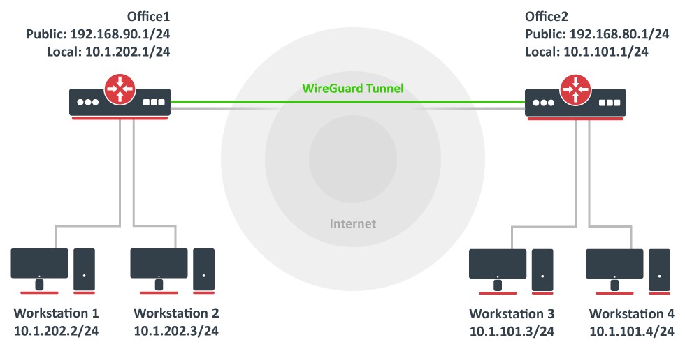
Consider the setup as illustrated below. Two remote office routers are connected to the internet and office workstations are behind NAT. Each office has its own local subnet, 10.1.202.0/24 for Office1 and 10.1.101.0/24 for Office2. Both remote offices need secure tunnels to local networks behind routers.
WireGuard interface configuration
First of all, WireGuard interfaces must be configured on both sites to allow automatic private and public key generation. The command is the same for both routers:
/interface/wireguard
add listen-port=13231 name=wireguard1
Now when printing the interface details, both private and public keys should be visible to allow an exchange.
Any private key will never be needed on the remote side device - hence the name private.
Office1
/interface/wireguard/print
Flags: X - disabled; R - running
 0  R name="wireguard1" mtu=1420 listen-port=13231 private-key="yKt9NJ4e5qlaSgh48WnPCDCEkDmq+VsBTt/DDEBWfEo="
      public-key="u7gYAg5tkioJDcm3hyS7pm79eADKPs/ZUGON6/fF3iI="
Office2
/interface/wireguard/print
Flags: X - disabled; R - running
 0  R name="wireguard1" mtu=1420 listen-port=13231 private-key="KMwxqe/iXAU8Jn9dd1o5pPdHep2blGxNWm9I944/I24="
      public-key="v/oIzPyFm1FPHrqhytZgsKjU7mUToQHLrW+Tb5e601M="
Peer configuration
Peer configuration defines who can use the WireGuard interface and what kind of traffic can be sent over it. To identify the remote peer, its public key must be specified together with the created WireGuard interface.
Office1
/interface/wireguard/peers
add allowed-address=10.1.101.0/24,10.255.255.2/32 endpoint-address=192.168.80.1 endpoint-port=13231 interface=wireguard1 \
public-key="v/oIzPyFm1FPHrqhytZgsKjU7mUToQHLrW+Tb5e601M="
Office2
/interface/wireguard/peers
add allowed-address=10.1.202.0/24,10.255.255.1/32 endpoint-address=192.168.90.1 endpoint-port=13231 interface=wireguard1 \
public-key="u7gYAg5tkioJDcm3hyS7pm79eADKPs/ZUGON6/fF3iI="
IP and routing configuration
Lastly, IP and routing information must be configured to allow traffic to be sent over the tunnel.
Office1
/ip/address
add address=10.255.255.1/30 interface=wireguard1
/ip/route
add dst-address=10.1.101.0/24 gateway=wireguard1
Office2
/ip/address
add address=10.255.255.2/30 interface=wireguard1
/ip/route
add dst-address=10.1.202.0/24 gateway=wireguard1
Firewall considerations
The default RouterOS firewall will block the tunnel from establishing properly. The traffic should be accepted in the "input" chain before any drop rules on both sites.
Office1
/ip/firewall/filter
add action=accept chain=input dst-port=13231 protocol=udp src-address=192.168.80.1
Office2
/ip/firewall/filter
add action=accept chain=input dst-port=13231 protocol=udp src-address=192.168.90.1
Additionally, it is possible that the "forward" chain restricts the communication between the subnets as well, so such traffic should be accepted before any drop rules as well.
Office1
/ip/firewall/filter
add action=accept chain=forward dst-address=10.1.202.0/24 src-address=10.1.101.0/24
add action=accept chain=forward dst-address=10.1.101.0/24 src-address=10.1.202.0/24
Office2
/ip/firewall/filter
add action=accept chain=forward dst-address=10.1.101.0/24 src-address=10.1.202.0/24
add action=accept chain=forward dst-address=10.1.202.0/24 src-address=10.1.101.0/24
RoadWarrior WireGuard tunnel
RouterOS configuration
Add a new WireGuard interface and assign an IP address to it.
/interface/wireguard
add listen-port=13231 name=wireguard1
/ip/address
add address=192.168.100.1/24 interface=wireguard1
Adding a new WireGuard interface will automatically generate a pair of private and public keys. You will need to configure the public key on your remote devices. To obtain the public key value, simply print out the interface details.
[admin@home] > /interface/wireguard/print
Flags: X - disabled; R - running
 0  R name="wireguard1" mtu=1420 listen-port=13231 private-key="cBPD6JNvbEQr73gJ7NmwepSrSPK3np381AWGvBk/QkU="
      public-key="VmGMh+cwPdb8//NOhuf1i1VIThypkMQrKAO9Y55ghG8="
For the next steps, you will need to figure out the public key of the remote device. Once you have it, add a new peer by specifying the public key of the remote device and allowed addresses that will be allowed over the WireGuard tunnel.
/interface/wireguard/peers
add allowed-address=192.168.100.2/32 interface=wireguard1 public-key="<paste public key from remote device here>"
Firewall considerations
If you have a default or strict firewall configured, you need to allow a remote device to establish the WireGuard connection to your device.
/ip/firewall/filter
add action=accept chain=input comment="allow WireGuard" dst-port=13231 protocol=udp place-before=1
To allow remote devices to connect to the RouterOS services (e.g. request DNS), allow the WireGuard subnet in the input chain.
/ip/firewall/filter
add action=accept chain=input comment="allow WireGuard traffic" src-address=192.168.100.0/24 place-before=1
Or simply add the WireGuard interface to the "LAN" interface list.
/interface/list/member
add interface=wireguard1 list=LAN
iOS configuration
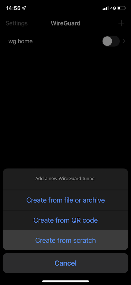
Download the WireGuard application from the App Store. Open it up and create a new configuration from scratch.
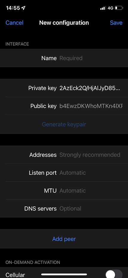
First of all give your connection a "Name" and choose to generate a keypair. The generated public key is necessary for peer's configuration on the RouterOS side.
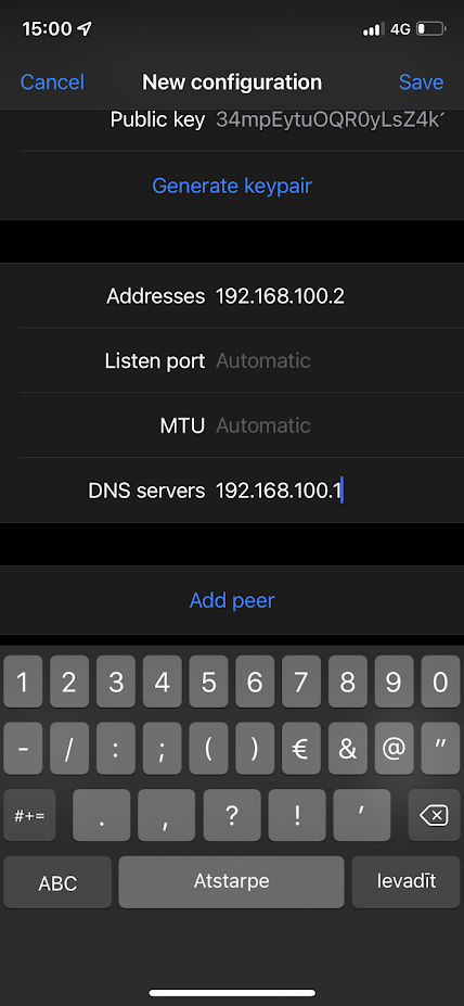
Specify an IP address in the "Addresses" field that is in the same subnet as configured on the server side. This address will be used for communication. For this example, we used 192.168.100.1/24 on the RouterOS side. You can use 192.168.100.2 here.
If necessary, configure the DNS servers. If allow-remote-requests is set to yes under the IP/DNS section on the RouterOS side, you can specify the remote WireGuard IP address here.
Click "Add peer" which reveals more parameters.
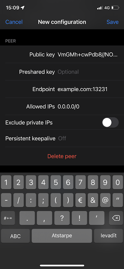
The "Public key" value is the public key value that is generated on the WireGuard interface on the RouterOS side.
"Endpoint" is the IP or DNS with a port number of the RouterOS device that the iOS device can communicate with over the Internet.
"Allowed IPs" are set to 0.0.0.0/0 to allow all traffic to be sent over the WireGuard tunnel.
Depending on your configuration, you may need to add a NAT
chain=dstnat action=dst- to-ports= protocol=udp in-interface= dst-port=
Windows 10 configuration
Download WireGuard installer from WireGuard
Run as Administrator.
Press Control+N to add a new empty tunnel, add a name for the interface, Public key should be auto-generated. Copy it to RouterOS peer configuration.
Add it to the server configuration, so the full configuration looks like this (keep your auto-generated PrivateKey in the [Interface] section:
[Interface]
PrivateKey = your_autogenerated_private_key=
Address = 192.168.100.2/24
DNS = 192.168.100.1

[Peer]
PublicKey = your_MikroTik_public_KEY=
AllowedIPs = 0.0.0.0/0
Endpoint = example.com:13231
Save and Activate
Multi-WAN setup
For WireGuard there is no server-client relationship, both ends can serve as an endpoint and both ends are streaming UDP handshake messages to each other if they have endpoints defined in their configurations (this is not always the case, as you can enable "responder" option in the peer settings, which will allow you to emulate server-client behavior, as "server" peer will only reply to the handshake messages from "client" peers and will not stream the handshake messages by itself).
Because of the nature described above of the tunnel establishment, handshake messages from different endpoints of the WireGuard tunnel are treated as two separate connections.
We need to take this into account for the setups with multiple paths to the "client" peer, as this can cause the "server" to reply to the "client" not via incoming route but via some other route, depending on the setup.
Further you can see a configuration example on how to address this behavior and ensure that the "server" uses incoming route to reply back to the "client".
Configuration example
This example does not include WireGuard interface configuration as it is applicable to both RoadWarrior and Site to Site setups with two WAN connections such as PCC setup.
For these rules to work as intended, you need to enable the "responder" option in WireGuard peer settings, as the "server" could send handshakes via the incorrect interface because routing was not marked.
/ip/firewall/mangle
add action=add-src-to-- chain=prerouting address-list=WAN2_WireGuard_clients address-list-timeout=1m dst-port=13231 in-interface=ether2 protocol=udp comment="add source IP address of WAN2 incoming WireGuard traffic to address list"
add action=mark- chain=output dst-address-list=WAN2_WireGuard_clients dst-port=13231 new-connection-mark=wan2 protocol=udp comment="mark WireGuard connection to the client peer by checking destination address from the address list"
add action=mark-routing chain=output connection-mark=wan2 dst-port=13231 new-routing-mark=wan2 protocol=udp comment="ensure that WireGuard traffic uses routing table associated with the WAN2 incoming interface"
add action=add-src-to-- chain=prerouting address-list=WAN3_WireGuard_clients address-list-timeout=1m dst-port=13231 in-interface=ether3 protocol=udp comment="add source IP address of WAN3 incoming WireGuard traffic to address list"
add action=mark- chain=output dst-address-list=WAN3_WireGuard_clients dst-port=13231 new-connection-mark=wan3 protocol=udp comment="mark WireGuard connection to the client peer by checking destination address from the address list"
add action=mark-routing chain=output connection-mark=wan3 dst-port=13231 new-routing-mark=wan3 protocol=udp comment="ensure that WireGuard traffic uses routing table associated with the WAN3 incoming interface"
/ip/firewall/nat
add action=masquerade chain=srcnat log=yes out-interface=ether2 comment="ensure that packet has source IP of WAN2 interface"
add action=masquerade chain=srcnat log=yes out-interface=ether3 comment="ensure that packet has source IP of WAN3 interface"
The first mangle rule is used to catch the source IP address by matching the destination port of the incoming WireGuard handshake and add it to the list which further will be used as a way to mark the outgoing WireGuard handshake. The timeout is used to ensure that in the future the same source IP address can establish a WireGuard tunnel using a different WAN interface.
The second mangle rule marks connections which are further used to mark routing and also ensures that the mark stays on the connection after the IP address is gone from the address list and the tunnel is established.
The third mangle rule is used to force the packet to use the correct routing table for the second WAN interface.
The last NAT rule is required to ensure that the packet is sent out with the correct source IP, as it is not adjusted by the mangle rules and if not implemented, the packet could have a different source IP depending on the setup.
As you can see, the rules are duplicated for WAN3, to ensure that the WAN3 interface is also usable with WireGuard.
This rule set ensures that WireGuard tunnel is established on the interface that received the incoming handshake.
2FA setup
HotSpot services can be bound to WireGuard interfaces in RouterOSv7. This allows administrators to combine WireGuard’s high-performance encryption with the HotSpot’s captive portal features, supporting additional user-level authentication via local database, User Manager, or RADIUS, and the OTP feature allows strengthening security even more.
Configuration example
Make sure the Wireguard interface is configured on your device:
/interface/wireguard> print
Flags: X - DISABLED; R - RUNNING
 0  R name="wg1" mtu=1420 listen-port=49422
      public-key="MikroTikMikroTikMikroTik="
Set up HotSpot on Wireguard interface:
/ip/hotspot> setup
Select to run HotSpot on
: wg1
or
/ip/hotspot/add interface=wg1
*Supported from 7.22
After HotSpot setup, once a Wireguard peer is connected, additional login to the portal will be required to proceed. Regular HotSpot username/password authorization could be used. For better security it is possible to utilize /ip/hotspot/user otp-password or /user-manager/user totp-password field. Add user with totp-secret:
/ip/hotspot/user/add name=peer1 totp-secret=HVR4CFHAFOWFGGFAGSA5JVTIMMPG6GMT
You can find multiple open-source totp generator tools that can provide you with an appropriate key and necessary options to import it into your "authenticator" app.
Once setup is complete, launch Wireguard on your device, and after successful authorization by the Wireguard/HotSpot server, HotSpot login page will be prompted and you will need to enter the HotSpot username and totp 6-symbol password (that is changing once in 30 seconds) from the "authenticator" app.
It is strongly recommended to use an HTTPS login page for HotSpot, and make sure the Wireguard peer has an option to verify the login page certificate.